Decoder Circuit Diagram Using Gates [diagram] Logic Diagram
How to design a 4 to 16 decoder using 3 to 8 decoder Design full adder using decoder and logic gates Decoder circuit binary diagram basic truth decoders logic circuitdigest gate block tables using basics working not saved following draw
Binary Decoders: Basics, Working, Truth Tables & Circuit Diagrams
Decoder circuit diagram 3 to 8 decoder logic diagram Decoder logic diagram and truth table wiring diagram schemas
What is a decoder? operation, types and applications
3x8 decoder pdfWhat is a decoder in logic circuits 4 to 16 decoder using 2 to 4 decoder verilog codeDecoder gates output inputs binary electrically4u.
Decoder circuit diagram using gatesDecoder circuit diagram using gates Binary decoders: basics, working, truth tables & circuit diagrams3-to-8 line decoder..

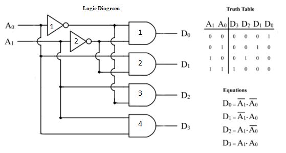
Decoder 3x8 enable
Decoder gates logic circuit technobyte2 to 4 decoder circuit diagram Decoder adder 3x8 function multiplexer logic binary inputs outputs block demultiplexer circuits nand designing segment3:8 decoder using gates.
Binary decoderDecoder logic rangkaian output equations instrumentation decodificador input vlsi nutshell demultiplexer combinational verilog circuitos inputs encoder bcd ingressi integrato coding 3 to 8 decoder logic diagramDigital and computer system [2].
![[DIAGRAM] Logic Diagram Of Bcd To Decimal Decoder - MYDIAGRAM.ONLINE](https://i.ytimg.com/vi/9UDQLgvpBR4/maxresdefault.jpg)
[diagram] logic diagram of bcd to decimal decoder
Decoder binary nand line gate codes[diagram] relay logic diagram Decoder, 3 to 8 decoder block diagram, truth table, and logic diagramVirtual labs.
Diagram of the decoder circuit based on not and and gates, extractedInstrumentation in a nutshell: decoder Decoder gates binary not line using output types applications implementation expression two construction adder halfBinary decoder used to decode a binary codes.

3 to 8 decoder logic diagram
Solved draw a digital circuit (using only decoder, or gates .
.


Decoder Logic Diagram And Truth Table Wiring Diagram Schemas | My XXX

Virtual Labs

2 To 4 Decoder Circuit Diagram

Binary Decoder used to Decode a Binary Codes

Binary Decoders: Basics, Working, Truth Tables & Circuit Diagrams

Binary Decoder - Construction, Types & Applications
![[DIAGRAM] Relay Logic Diagram - MYDIAGRAM.ONLINE](https://i2.wp.com/www.electroniclinic.com/wp-content/uploads/2020/05/3-to-8-line-decoder-logic-diagram.png?fit=6700%2C5719u0026ssl=1)
[DIAGRAM] Relay Logic Diagram - MYDIAGRAM.ONLINE
INSTRUMENTATION IN A NUTSHELL: DECODER